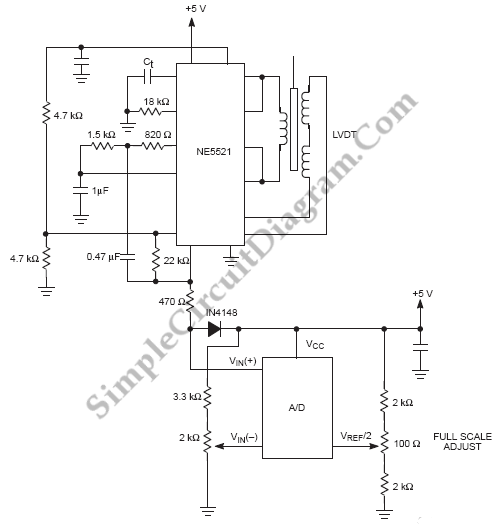
Digitizing a LVDT Transducer Interface Output
Digitizing transducer interface output voltage is shown on circuit diagram below. The transducer in this case is the NE5521, an LVDT (Linear Variable Differential Transformer) Signal Conditioner. To ensure that the input to the A/D does not go excessively beyond the supply voltage of the A/D, this device is use the diode at the A/D input. For a better description of the operation of the part, you can see the NE5521 data sheet.

Determine the range of voltages that the transducer interface output will take on to adjust the full scale of the A/D. LVDT core is set for null and the Zero Scale Scale Adjust Potentiometer for a digital output from A/D of 1000 000 is set. The LVDT core for maximum voltage from the interface is set and then the Full Scale Adjust potentiometer is set so the A/D output is just barely 1111 1111. [Source: NXP Application Note]