Sound Controlled Activated Triggered LED
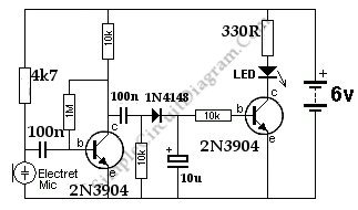
When the microphone detects a loud sound, this circuit will turn the LED on. The “charge-pump” section consists of the 100n, 10k, signal diode and 10 uF electrolytic. Here is the schematic diagram of the circuit:

The charge pump section has two functions: rectifying and multiplying the signal voltage. To illuminate the LED, a signal on the collector of the first transistor is passed to the charge pump section and finally drive the second transistor.