TMP01 4 to 20mA Current Loop
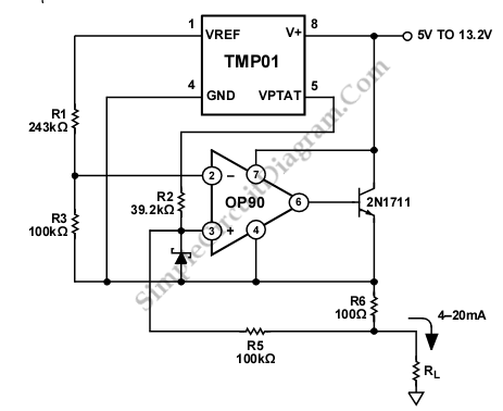
This is a 4 mA TO 20 mA CURRENT LOOP circuit. This circuit is used to transmit a signal over long distances. The accuracy of this circuit is not compromised by voltage drops across the line. This circuit must consume less than 4 mA, because the remote end must receive all of its power from the loop. This circuit require 5V input voltage, the quiescent current of OP90s is 20 µA maximum and the TMP01 is 500 µA maximum. Here is the schematic diagram of the circuit:

Temperature setting pins and the open collector outputs can be connected to do any local control of switching. The current is calibrated to 4 mA at a temperature of -40°C, to 20 mA for +85°C and proportional to the voltage on the VPTAT. The output current is determined by folowing equation:
Io=1/R6*((VPTAT*R5/R2)-(VREF*R3/(R3+R1))*(1+R5/R2))
Temperature coefficient of the output current is 128 µA/°C. This circuit uses The OP90 due to its high accuracy and its ability to operate on a single supply.
TO determine the values of resistor, the ratio of R5 over R2 must give a variation of Io from 4 mA to 20 mA. The value of R3 and R1 is determined by substituting 4 mA for Io and 1.165 V for VPTAT. A 10k trimmer potentiometer is used to determine initial accuracy, to be inserted in series with R3, and R3 should be lowered to 95k. The potentiometer should be adjusted to produce an output current of 12.3 mA at 25°C. [Source: analog.com]