LM2917 Automotive Tachometer
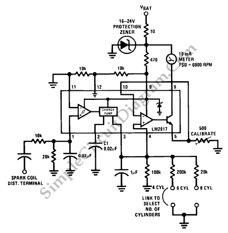
Variable reluctance magnetic is not derive all inputs. For example in spark ignition engines, the inputs are derived from the spark coil. Below is figure of an interface circuit for this situation. We can set up any number of cylinders using this tachometer by linking the appropriate timing resistor as illustrated.

We can use a 500ohm trim resistor to set up final calibration. A protection circuit composed of a zener diode and a 10 ohm resistor is also shown as a safety precaution against the transients which are to be found in automobiles. [Circuit’s schematic diagram source: National Semiconductor Application Note]