Zener Diode Voltage Regulator
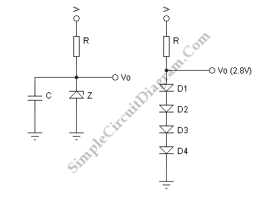
The figure below show us a zener regulator. The essential component is the dropping resistor R which the value given by (V-Vo)/I, where I is the desired output plus 10%. As long as the supply voltage V is constant, the current in thner current drops to zero, and we is resistor is constant and is shared between the Zener and the load. The Zener current only consist of the 10% extra when the load is removed, all the current passes through the Zener and with the maximum load. Then it ceases to regulate if the Zehave an ordinary voltage divider. To make sure this doesnt happen, we allow about 10% extra. The power dissipated in both the dropping resistor and the Zener diode must be considered, and suitable power ratings applied. We can find small zeners in 1/2W and 1W size. The 1N5231 is 1/2W while the 1N4733 is a 1W Zener. Both have a Zener voltage of 5.1V.
You can measure the output voltages for a range of load resistances from infinity down to 100 ohm if you set up a 5.1V regulator with R=100 ohm (1/2 W!) and a 1N4733. In this case, the current in R is about 69 mA. You will see that the voltage is no longer held at about 5 V if you connect a 51 ohm (1/2W) resistor as a load. At the higher load currents, the voltage drops somewhat because the Zener voltage changes slightly with current (as a load current increases, the Zener current decreases, and so does the Zener voltage). The slope is expressed as the Zener resistance. The change in this voltage is divided by the change in current. I measured about 5 ohm (which is really the Zener resistance in paraller with R) in this case. This is a pretty good voltage source. It is drawn with a despiking capacitor which will not explained here. The input voltage to the Zener regulator can vary. Thats not affecting the outpul voltage. In this case, only the total current is changed.
A smaller voltage is required, less than 3V, one possibility is a string of diodes as shown in the figure. The diodes are biased in the forward direction. They can be used as a voltage regulator since the current increases rapidly with voltage. The incremental resistance of each diode is about 50 ohm/I. I here stands for the diode current in mA. In a transistor, 25 Ohm appears instead of 50 Ohm diodes are made somewhat differently. The actiual figure is somewhere between 25 and 50. That’s all depending on the diode. We choose a diode current of 20 mA in this case, so the internal resistance of this regulator is 4 x 2.5 = 10 ohm, in parallel with the dropping resistor. We can use either, the signal or the rectifier diodes. The 1N4001 will handle diode currents up to 1 A. There is no consequence of reverse breakdown voltage here (usually an important parameter).
