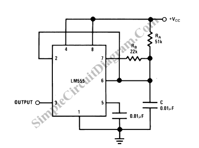
555 Oscillator With 50% Duty Cycle
To generate 50% active factor (duty cycle) using 555 IC, we can use two diodes to separate the charging and the discharging path. With no diodes, we can also generate 50% duty cycle using 555 IC by configuring the circuit as shown in the schematic diagram.

The high state period is similar to regular configuration, t1 = 0.693 RA C, and the low state period is equal to t2=[(RA.RB/(RA+RB)].C.Ln[(RB-2RA)/(2RB-RA)]. Finally, we can get the total period of t1+t2, or the frequency of 1/(t1+t2). Please be aware that the circuit will work only if RB is smaller than 1/2 RA. Higher value of RB cannot bring the level of pin 2 down to 1/3 VCC and trigger the lower comparator. [Circuit’s schematic diagram source: National Semiconductor Application Notes]