Overvoltage Protection with LT1018
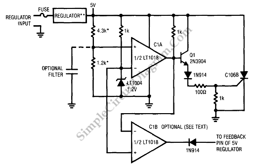
Sometimes, the regulator does not work well so the regulator generate overvoltage that will destroy the system. To prevent system damage, a overvoltage protection circuit should be used. The overvoltage occurred when the regulator connects the raw DC supply to the 5V rail. This failure can be occurred due to the feedback loop opens up or the pass transistor shorts. The C1A is a comparator that compare the 5V supply to the LT1004 reference via resistive divider. Here is the schematic diagram of the circuit:

The SCR is turned on via Q1 when the supply rises beyond 5.5V causing the C1A’s output. The downstream fuse is blown up by the SCR current which the peaks of the current almost 6A. If the overvoltage is caused by error amplifier malfunction or feedback error the C1B pulls the supply feedback node low which will make sure the minimum pass transistor on-resistance.
The range time of the supply peaks from begin to shutdown is about 5µs that will cause the maximum overvoltage occurred is 5.7V. For the different trip values, the 4.7K-1.2K can be changed. To suppress transistor the optional filter can be used. To remove false tripping on power-up, the dioda combined with the LT1028’s 1.2V minimum supply at SCR’s gate. [Circuit’s schematic diagram source: Linear Technology Application Note]