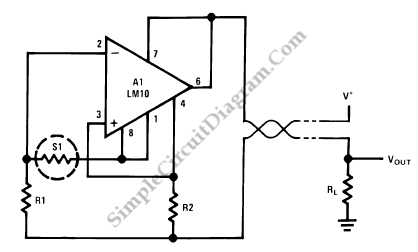
Resistance Thermometer Current Loop Transmitter
Resistance temperature sensor (RTD, resistive temperature device) comes in NTC (negative temperature coefficient) and PTC (positive temperature coefficient) forms. A schematic diagram below show a signal conditioner circuit for such thermometer. This sensor conditioning circuit works in current mode (current loop) and the amplifier inside gives a current output that is inversely proportional with the sensor’s resistance.

This temperature transmitter circuit is loop powered, so you don’t have to provide separate power supply wires for power supply and for the output signal. Provide cable pair to supply the circuit at the remote, then measure the current to get the sensor’s temperature reading. Measuring the current can be done by passing the loop through a small resistor at the receiver side (at the power supply side) and measure the voltage drop across the resistor to get the temperature value. [Circuit’s schematic diagram source: National Semiconductor Application Note]