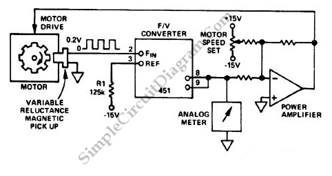
F/V Converter in CLosed Loop Motor Speed Control System
Closed loop or servo system has the ability to stabilize the controlled plant at a specified operating condition. The plant, the controlled sub-system, can be any form of controllable system. In motor control system, the plant is off course a motor. The basic principle of automatic control mechanism in motor control is by monitoring the real speed of the motor, compare it with the reference, and manipulate the power supply to make the motor correct the speed toward minimizing the error between actual speed and the reference. An example of closed loop motor control system is shown in the block diagram below:

Motor Speed Sensor
The speed sensing is done by a magnetic pickup sensor. This speed sensor type is widely used in such system because of simplicity and robustness. It basically consist of a coil wounded around a permanent magnet. When a ferromagnetic material (usually a rotating gear) is moving around the magnetic field, it change the magnetic flux around the coil. Any change of magnetic flux around a coil in a right direction will produce electromotive force or voltage on the coil. This voltage pulse will have frequency that is proportional to the rotating speed.
VF/ Conversion and Closed Loop Motor Control Mechanism
The pulse from the speed sensor is then converted to a voltage that is linearly proportional to the actual speed of the motor using a V/F converter. Using a summing op-amp, this speed information is then compared with a reference voltage that set the desired operating speed of the motor. Let say the potentiometer set the reference voltage at -5V, and the motor is currently at zero speed. Since the actual speed would be indicated by sensor would be zero volt (after v/f conversion), the output of the power amplifier will be almost at positive saturated voltage, since the inverting input (-5V) is much lower than the non-inverting input. With the output voltage at full capacity, the motor now will speed up and the the speed voltage will increase. As the speed voltage increase, the inverting input also increase to approximate the non-inverting input level (zero volt). Motor speed continue to increase then the inverting input voltage will reach the noninverting input level (zero volt). At ideal condition, after the motor speed reach the desired speed, the power amplifier will output a zero volt (no additional power is delivered to the motor), and the motor will run continuously keeping its constant speed. If then the motor slightly slows down then the inverting input won’t be equal to the non-inverting input and the amplifier will produce voltage to power the motor again, correcting its speed again. This ideal condition will never happen in reality, since there always be slip error between the actual and the desired speed.
Slip Error in Proportional Motor Control
The controller circuit is a proportional controller that only produce power control output when there is a difference (slip) between the actual and the desired output. Ideal motor can be imagined as rotating freely, accelerating infinitely when a power is applied and no slowing down if the power supply is removed. Because real motor is far from ideal motor, keeping the motor speed at a constant value need a certain amount of power, so there will always be slip to produce the needed amount of power.