74S124 High Frequency VCO with Varactor
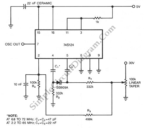
The following schematic diagram shown a conventional which is modified to become a VCO (voltage-controlled oscillator) circuit. By replacing the conventional fixed capacitor with a variable capacitance diode (varactor), we can turn a 74S124 multivibrator into a wide-band VCO. High speed logic 74S series is used here to enable this circuit for high frequency operation. Here is the schematic diagram of the circuit:

The need of a relatively high voltage source, the 30 V biasing voltage that the diode requires is the only disadvantage of this scheme. We can use lower voltage for this, but it means the VCO would be no more wide-range. Capacitors C1 and C2 couple the Philips BB909A variable capacitance diode to the 74S124. This capacitors can be selected to different values to accommodate different frequency range. Use C1 = C2 = 47pF for 6.8 to 72 MHz, and use C1 = C2 = 22nF for 2.2 to 65 MHz. R1 and R2 are large enough to isolate ground and control voltages from the timing capacitors. The potentiometer is used as a voltage divider for controlling the capacitance of varactor, thus controlling the frequency of this VCO circuit. This potentiometer can be omitted if we control this circuit using voltage signal from other devices, replacing the center tap of this potentiometer.