Spectrum Analyzer Adapter for Oscilloscopes
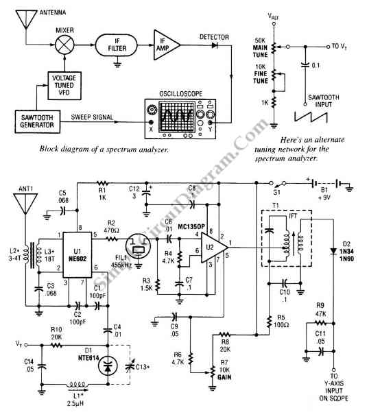
The circuit shown in the following schematic diagram is a simple spectrum analyzer adapter circuit for oscilloscopes. This circuit can be used for scanning or monitoring a segment of radio spectrum or amateur band. Inside this circuit, an NE602 mixer chip generates a 455-kHz IF signal. The U2 is used to amplify the signal. Then the amplified signal is fed to Y axis of an oscilloscope and detector D2. The horizontal axis input of scope is driven by Vt. Here is the schematic diagram of the circuit:
 Using L2 and L3 shown, the frequency range of this circuit is 10 to 15MHz. L1 is homemade or commercial variable inductor. L3 and L2 are T-50 or T37 toroidal cores. [Circuit’s schematic diagram source: seekic.com]