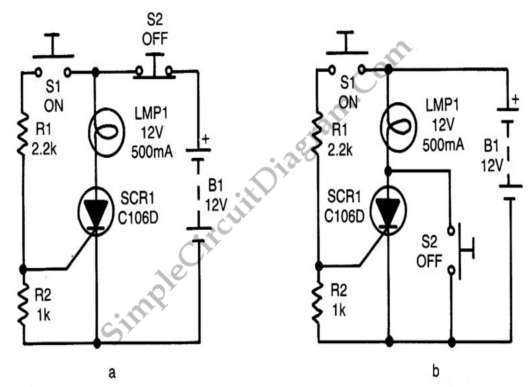
Two Methods for Push Button Controlled Power Switch
On these two following circuits, we can latch on the SCR (and thereby the lamp) by momentarily closing S1, thereby feeding gate drive to the SC via R1. The gate is tied to the cathode via R2 to improve circuit stability in both circuits. It can be turned off again after the SCR turns on only by temporarily reducing anode current below the device’s IH value. This can be done by opening S2, by using S2 to short the anode and cathode terminals of the SCR briefly. Here is the schematic diagram of the circuit:
