Long Distance Video Wire
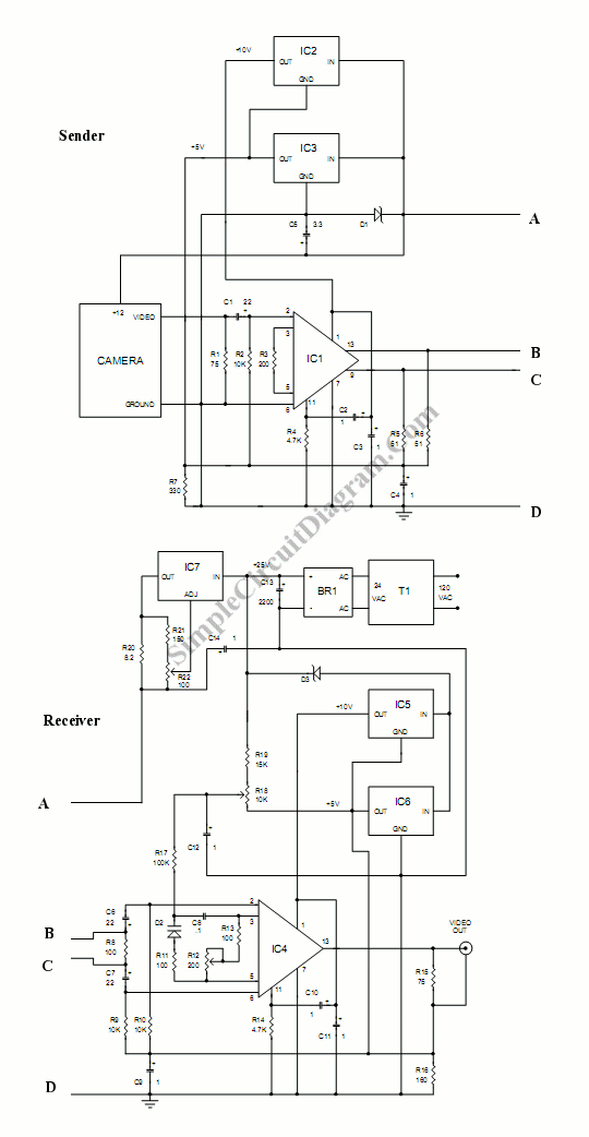
This circuit is used to connect the camera with very log wire. This is actually a video amplifiers. This circuit consist of two part, they are sender part and receiver part. At the sender part, this circuit uses an amplifier to make a stronger signal. So the signal can be transmitted through the long cables. To transmitted the signal, this circuit uses balanced mode, where two wires are driven in the opposite phase. Here is the schematic diagram :
The resistance of a typical four conductor flat 28 gauge telephone wire is about 7 ohms per 100 feet. Since voltage drops appear in both the plus and minus power supply leads, the total series resistance is about 14 ohms per 100 feet. Maximum allowable wire length depends on the total current requirements of the camera and send board. Using a camera that draws 100 ma, for example, a total current of about 180 ma is required and therefore a maximum of approximately 500 feet of 28 gauge flat telephone wire can be used. If a longer wire is needed, the round type of 22 gauge four conductor telephone wire offers much lower resistance. Its resistance per 100 feet is approximately 3.3 ohms total for both the positive and negative power wires. Using this wire and a 100 ma camera, the wire length can be approximately 2000 feet.
Parts:
* C1 – 22 mfd 6.3 volt tantalum
* C2, C3, C4, C9, C10, C11, C12 – 1 mfd 16 volt tantalum
* C5 – 3.3 mfd 16 volt tantalum
* C6, C7 – 22 mfd 16 volt tantalum
* C8 – .1 mfd 50 volt metalized film
* C13 – 2200 mfd 50 volt electrolytic
* C14 – 1 mfd 50 volt tantalum
* R1, R15 – 75 ohms 1/8 watt
* R2, R9, R10 – 10K 1/8 watt
* R3 – 200 ohms 1/8 watt
* R4, R14 – 4.7K 1/8 watt
* R5, R6 – 51 ohms 1/8 watt
* R7 – 330 ohms 1/8 watt
* R8, R11, R13 – 100 ohms 1/8 watt
* R12 – 200 ohms potentiometer
* R16 – 160 ohms 1/4 watt
* R17 – 100K 1/8 watt
* R18 – 10K potentiometer
* R19 – 15K 1/8 watt
* R20 – 8.2 ohm 1/2 watt
* R21 – 150 ohm 1/8 watt
* R22 – 100 ohm potentiometer
* R dummy – 100 ohm 2 watt
* D1 – 12 volt 1 watt zener diode
* D2 – Motorola MVAM109 tuning diode
* D3 – 10 volt 1 watt zener diode
* BR1 – 1 amp 400 volt DIP bridge rectifier
* IC1 – Maxim MAX435 dual output amplifier
* IC2, IC3, IC5, IC6 – 78L05 voltage regulator
* IC4 – Maxim MAX436 single output amplifier
* IC7 – LM317 adjustable voltage regulator
* J1 – RJ11 6P4C telephone jack with leads
* J2 – RJ11 6P4C board mount telephone jack
* J3 – chassis mount angle coaxial F connector
* T1 – 24 volt AC 400 ma adapter transformer
* eight 6-32 X 1/4 inch screws
* rubber grommet for 1/4 inch hole
* 2.2 X 3.3 X 4 inch metal enclosure with vent holes
* four conductor telephone wire with RJ11 plugs
* TO220 5 watt clip on heat sink
* four threaded spacers 6-32 X 1/2 inch long
The MAX435 transconductance amplifier is used as the core of this circuit. This circuit has wide bandwidth feature that is suitable for video signal application. To make sure that any noise exposing the cables would cancel each other at the receiver, this circuit uses balanced mode. [Schematic diagram source: aeiproducts.com]
