4mA–20mA Loop Powered Temperature Sensor
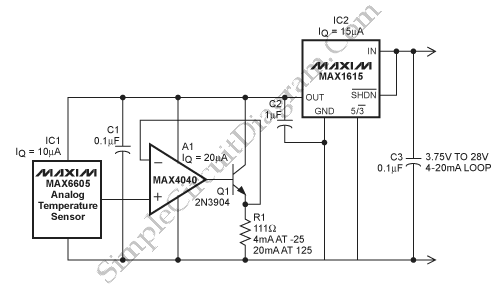
This circuit is used to allow a 4mA–20mA to power an analog temperature sensor. To provide a 4mA–20mA output over a 3.75V–28V compliance range this circuit uses an op-amp, low-dropout linear regulator, transistor and an analog temperature sensor. It is powered by the loop with the only consequence being a slight offset error because of the quiescent current of the devices. Here is the circuit :

This circuit uses MAX6605 as a temperature sensor that feeds the transistor/op amp combination, Q1 and A1, and R1 as the load on the amplifier. The MAX6605 has a scale factor of 11.9mV/°C and an offset of 744mV at 0°C. To provide the best possible fit of the temperature range of IC1 to the 4mA–20mA output this circuit uses R1. Besides that, this circuit uses MAX1615 to provides the compliance at the voltage input required for connection to the 4mA–20mA loop and regulates the voltage to the op amp circuit and sensor. The proportional output current scale factor considering 45µA current in light of the scale factor is :
4mA–20mA Output Current Scale Factor = (11.9mV/°C)/R1
[Source: maxim-ic.com]