PLL Oscillator for Medium Wave Frequency
What is a PLL oscillator?
PLL stands for phase locked loop, and this means a control method by comparation of the controlled plant or system to a reference clock or oscillator, that the plant is controlled to synchronize the clock. PLL has been widely implemented in motor control application, to make the motor rotates at very precise speed, even at very precise phase. When PLL is implemented to make a PLL oscillator, the common goal is to get very precise oascillation as we seen in the crystal oscillator, but with very low distortion of sine wave output as we see in LC based oscillator circuit.

How PLL Oscillator Works
The block diagram of a PLL Oscillator should contain a stable reference crystal clock, a phase error detector, and a voltage controlled oscillator (VCO). The phase error detector will detect the difference of the reference phase and the VCO output phase, and the output will be proportional to the phase difference. This phase difference signal is then used to control the VCO, if the frequency of VCO output is not equal to the reference, the phase error signal will try to correct the VCO frequency by feeding more voltage to the VCO until the phase difference is equal to a level to maintain the VCO frequency to be same with the reference clock.
Frequency Multiplication of PLL Oscillator
By adding a divider between the VCO output and the phase difference detector, now the PLL will maintain the divided VCO frequency to be equal eith the reference, and it means the VCO output will be maintained at X times the reference, where x is the division of the divider inside the loop. Using this way, the PLL oscillator is capable to obtain very precise frequency steps at the output by programming the divider.
PLL Oscillator Circuit
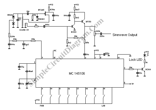
The schematic diagram of the circuit shown in the above figure is simple since the phase detector and the divider is equipped in a single chip MC145106 IC, and only VCO is required as the extrernal circuit. The crystal (xtal) is 4608 kHz for Europe broadcasting standard, and 5120 kHz for USA. The test point TP at pin 5 gives the center frequency of th crystal, and can be used for calibration purpose.