Crystal Tester
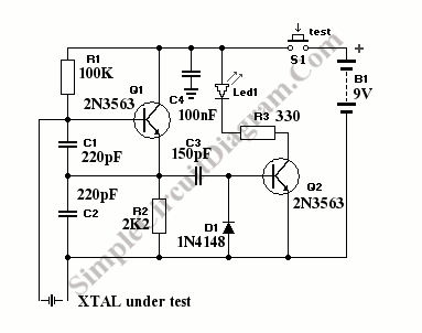
Quartz crystal tester is needed if you want to know whether the crystal is good or bad (broken). This crystal tester gives LED light indicator. If the crystal under test is good, the LED indicator will light, and stay off if bad. The circuit is simple and easy to build, here is the schematic diagram:

This crystal tester circuit use only two transistor, the first transistor is used as an oscillator, and the second one is employed as the detector. The oscillator will produce a high frequency signal if a good crystal is connected at the tester’s probes. This AC signal will flow through C3 and activate the base of Q2, and cause the Q1 to light the LED indicator, tell us if the crystal is good. The D1 is used to provide the back path of the AC signal. If the crystal is bad, the oscillator won’t produce AC signal on Q1 output, and there will be only a DC voltage on Q1 emitter. This DC voltage will be blocked by C3, so the Q2 won’t be triggered to light the LED indicator. That’s how the crystal tester works, very simple.