Power Path Management Battery Charger
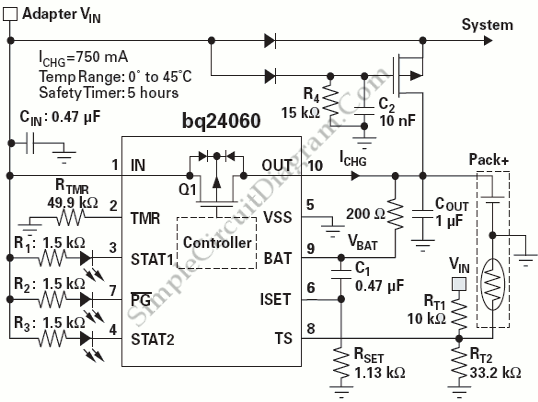
Powering the system is required by many applications while charging the battery simultaneously. Interaction between the system and charger may result in a false charge stoppage caused by the safety timer when the system is directly connected to the battery-charge output. The circuit diagram below shows a typical application circuit that removes such issues.

This circuit has two independent power paths, one to charge the battery and one to power system. The battery discharge MOSFET is turned on after a time delay set by R4 and C2 when the AC adapter is not available. As the result, battery will provide power to the system. [Source: Texas Instruments Application Note]