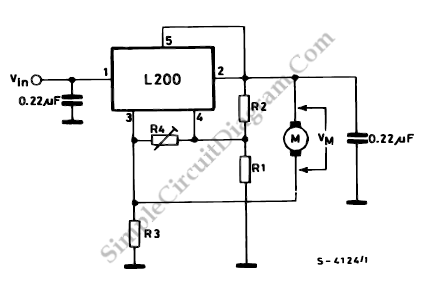
L200 DC Motor Speed Control
This diagram tells us about how to use L200 device for the speed control of permanent magnet motors.

By means of R1 and R2, we can obtain the desired speed, proportional to the voltage at the terminal of the motor.
Vm= Vref (1+R2/R1)
We can use this following equation to obtain better compensation of the internal motor resistance, which is essential for good regulation.
R3< (R1/R2).RM
This equation can be used with infinite R4. The motor speed can be increased without altering the ratio R2/R1 and R3 if R4 is finite. This voltage acts on R2 as a constant current source variable with r4 since R4 has a constant voltage (Vref) at it’s terminals, which does not vary as R4 varies. The voltage drop on R2 thus increases, and by the voltage at the terminals of the motor, the increase is felt. The voltage increase at the motor terminals is :
Vm = (Vref/(R4+R3)).R2
The circuit realization for 30 W motor (with RM = 4 ohm) can be obtained using R1 = 1 kohm, R2 = 4.3 kohm, R4 = 22 kohm and R3 = 0.82 ohm. [Source: STMicroelectronics Application Note]