All-Pass Filter (1st Order)
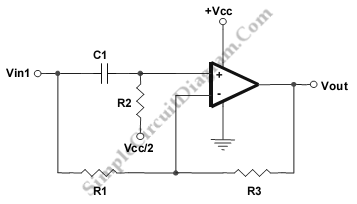
This is a 1st order ALL pass filter circuit. All frequencies are allowed at the same gain by this circuit. Here is the schematic diagram of the circuit:

We can change the signal’s phase using this circuit. This circuit can be used to correct the phase of the signal as well. At F(90) this circuit has a 90° phase shift. At high frequencies the phase shift is 180° and 0° at dc. The component values R1 = R2 = R3 = R, with F(90) = 1/(2pR*C1) . F(90) is the frequency where we expect for 90 degrees phase shift. [Source: Texas Instruments Application Note]