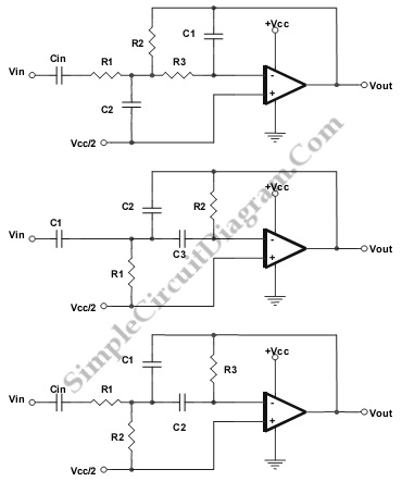
Low-, Band-, and High-Pass Single Supply Multiple Feedback Filter
This is Low-, Band-, and High-Pass Single Supply Multiple Feedback Filter circuit. This circuit uses MFB topology, which has some advantages and disadvantages. The advantages of MFB topology are low cost, easy to implement and very versatile. The disadvantage of MFB topology is it has complex calculation. This circuit uses a unity gain Butterworth, so the circuit will give a close approximation. Here is the circuit:

LOW PASS:
unity gain Butterworth
R1 = R2 = R/squareroot(2)
R3 = R/(2*squareroot(2) )
C1 = C
C2 = 4C
Fo = 1/(2pi RC)
HIGH PASS
Unity Gain Butterworth
Fo = 1/(2 piRC)
C1 = C2 = C3 = C
R1 = 0.47R
R2 = 2.1R
BAND PASS
Gain = 2.3 dB
R3 = 100R
R2 = 0.001R
R1 = 10R
C2 = C
C1 = 10C
Fo = 1/(2.32 piRC)
[Source: Texas Instruments Application Note]