UHF Antenna Booster
Antenna Booster Circuit
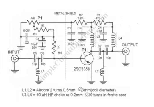
This antenna signal booster works for TV receiver in UHF band (400-850MHz). This antenna booster gives around 10 to 15 dB amplification. Here is the schematic diagram of the circuit:

This antenna amplifier circuit need special attention for the layout, the transistor circuits should be shielded from the input circuit (as shown with the dashed line), and the wiring should be kept as short as possible to prevent parasitic inductance and capacitance. P1 should be adjusted to get the best reception, and this adjustment should make the current consumption setting of about 5-15 mA. This antenna amplifier circuit should be installed as close as possible to the antenna, use the shortest possible cable for this, while you can use a very long cable from the output of this booster circuit to the television.
Special Power Supply for Antenna Booster
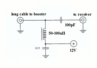
You can see that the circuit has no power supply input, and yes, this circuit is powered via the output signal cable. Because of this, you need a special 12 v power supply for this. Just use a conventional power 12 dc power supply, connect an RF choke or small inductor around 50-100uH, now you get two point: the plus from the choke/inductor and the ground from the power supply. This two points is the connected to the output of the antenna booster circuit with the coaxial cable (the long cable from power supply to the circuit).

The signal for the television is tapped from the ground and the connection between the inductor/choke and the long cable to the booster circuit. Insert a small capacitor (100pF) between the television and the power supply to block the DC voltage, you can insert in the ground line, but the recommended is in the postive line.