Basic FET Amplifier
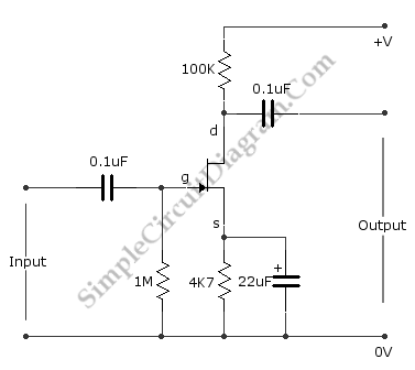
This is The Fet Amplifier circuit. This circuit uses FET transistor. The gate of the FET must be negative with respect to the source, so a bias can be achieved in the following manner. The voltage that is across the source resistor is developed by the drain current flowing through the source resistor. Due to that action, the emitter become positive with respect the zero volts rail. Here is the schematic diagram of the circuit:

The fet is biased correctly, since the current does not flow at gate make the gate has a zero volts. So, the gate is negative with respect to the source because the source is positive with respect to the gate. The drain current is controlled by the signal voltage that is applied to the gate.
The drain current will be decreased when the signal goes less positive. It will make the drain voltage goes more positive because just a little voltage across the drain resistor. The drain voltage will goes more negative and more voltage across the drain resistor when the drain current is increased because the signal voltage goes more positive. So, the drain voltage does the opposite of the gate voltage.