5V FET Voltage Regulator and How It Works
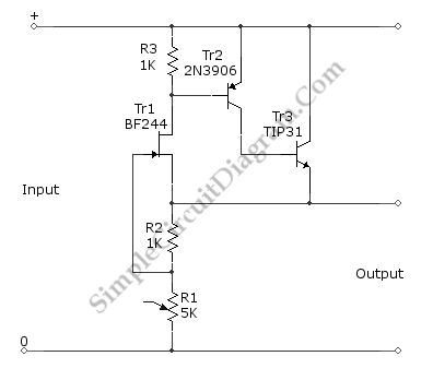
Using a FET and two additional transistors (cascaded to improve the gain), a 5V FET voltage regulator can be formed. The additional Tr2 and Tr3 transistors will improve the output current handling and decrease the output impedance. The output voltage deviate only 0.1V for load current change as high as 60 mA which is caused by load resistance changes that affect gate-source voltage of FET through R2 and R1. Here is the schematic diagram of the circuit:

The regulation principles (how it works) can be explained in a simple way: Initially, there will be no current at R2, so the gate-source voltage is zero, so the FET will be conducting. As soon as the FET is conducting, a voltage is developed across R2, and this cause the gate-source voltage becomes negative. This negative voltage is going more negative as the voltage increases until the the gate-source voltage reach the cut-off level of the FET. At this point, the voltage across R2 is stabilized since adding more current will make the FET decrease its conductivity, and decreasing the current will make the gate voltage rise (more positive) and increase the FET’s conductivity. What is done by Tr2 and Tr3 transistors is nothing more than boosting the FET’s action, whenever the FET try to conduct more current, the voltage at R3 will increase and make the transistor supply additional current to the output. R1 can be trimmed to adjust the output voltage. The basic principle is that the FET will keep the voltage across R2 to be equal to the FET’s cut-off level, and almost all current flowing through R2 will flow through R1 since the flow to the FET’s gate can be neglected. As we can see the output voltage is the sum of voltage across R1 and voltage across R2, so the output voltage will be:
Vout=Current * (R1+R2);
Vout=[(Vcut-off)/R1]*(R1+R2);
Let say if the cut-off voltage for the FET is -2V, then we have to trim R1 at 1.5k to get 5V output.