Basic Circuit Makes RGB Color Organ
The idea of a color organ is that any sound, including musical sound, can be transformed into light. As stated by wave theory, both music and light have similar properties: frequency. Any note, or combination of notes (chord) can be then mapped to a color. A low frequency sound can be associated to red or near infrared, and high frequency sound can be mapped to blue color light. A very simple color organ might use only the volume / amplitude to drive a light bulb, giving light intensity that is proportional to the volume.

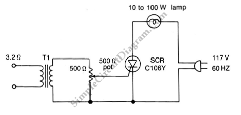
The above schematic diagram shows a basic color organ circuit. This circuit consist of transformer, SCR and potentiometer. The transformer T1 is used to keep the 117-V line voltage from the amplifier connections. The values of Transformer T1 is the range of 500/500 to 2500/2500 ohms. The SCR is connected to ground. For beat listening, the potentiometer should be adjusted until the lamp starts to throb. for normal listening level, potentiometer R1 should be set “off” and then adjust the amplifier volume control.
To modify this circuit into a real color organ / RGB color organ, at least we need three units of this circuit, one for red light bulb, one for green, and one for blue. The red light should be driven by bass signal (low-pass filtered), the green should by mid-range signal (band-pass filtered), and the blue by treble signal (high-pass filtered).