High/Low Voltage Probe
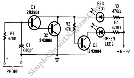
Simple voltage probe circuit shown in the schematic diagram below very useful in testing, testing, or troubleshooting discrete or integrated circuits, especially logic circuitry. This voltage probe circuit gives two indication, “high” or “low”. Here is the schematic diagram of the circuit:

When the “high” condition is probed, Q2 and Q1 transistor will be activated shorting R2 and LED1 to ground. This make LED1(red) glows and LED2 (green) off. If the voltage sensed by the probe is “low” then Q1 and Q2 transistors will be in inactive state, and Q3 will be biased through R2 and LED1. This bias make Q3 active and turn LED2 on, but this bias current is small enough to glow LED1, so LED1 will be seen in off condition. The term “high” and “low” is actually determined by the bias voltage needed by Q1 and Q2 to activate them. This will be 2 x 0.6V (about 1.2V), so “high” is an interpretation of >1.2V and “low” is when the voltage <1.2V. [Circuit’s schematic diagram source: seekic.com]