Two Wires-Stepper Motor Controller
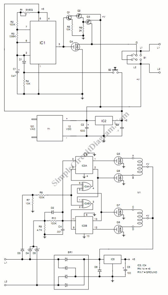
To get a position control that are low cost, accurate and simple we can use stepper motor. To drive it we can use a circuit mounted close to the motor, and to control it we can use remote control circuit via long cable. The power for both motor and the driver circuit is carried over two wires the same wires that carry the control signal.here is the schematic diagram of this circuit:

To step the motor and control its speed, this circuit uses LMC555 CMOS timer integrated circuit (IC1) that generates 200 microsecond pulses. R1 variable resistor is used to change the speed of the motor. If we change the value of R1, the frequency of this pulses will change, and the speed of motor will change.
At the output of IC1 (pin 3), a negative going clock pulse drive the gate of IRL530N (Q1) power FET that momentarily disconnects and turns OFF the driver board from ground. To step the motor, the motor driver uses the signal that sent by this power interuption. The polarity of the voltage applied to the driver circuit through interconnect lines L1 and L2 is used to control the rotation direction.
MPSA55 PNP transistors( Q3 and Q4) and MPSA05 Bipolar NPN transistor (Q2) invert the pulse from pin 3, pull the drain of Q1 UP when it is OFF. Toggle switch S1 sets its direction by switching polarity. To starts and stops the motor this circuit uses push button S2 by turning the clock on and off.
Parts
- C1 – .47 MFD 35 volt tantalum
- C2 – 1000 MFD 35 volt electrolytic
- C3 – .1 MFD 50 volt metalized film
- C4 – .001 MFD 50 volt metalized film
- C5 – 100 MFD 16 volt electrolytic
- R1 – 5MEG potentiometer
- R2, R8, R10 – 100K 1/8 watt 5%
- R3 – .56K 1/8 watt 5%
- R4, R5, R7 – 10K 1/8 watt 5%
- R6 – 2K 1/8 watt 5%
- R9 – 4.7K 1/8 watt 5%
- Q1 – MPSA05 NPN transistor
- Q2, Q3 – MPSA55 PNP transistor
- Q4, Q5, Q6, Q7, Q8 – IRL530N Hexfet
- D1, D2, D3 – 1N914 silicon diode
- D4, D5 – 1N4752 zener diode
- D6 – 1N4004 rectifier
- BR1 – 2 AMP 400 volt bridge rectifier
- IC1 – LMC555 CMOS timer
- IC2, IC5 – 78L05 5 volt regulator
- IC3 – CD4013 dual D flip flop
- IC4 – CD4070 quad exclusive or
- S1 – momentary N/O push button switch
- S2 – double pole double throw toggle switch
- T1 – DC or AC adapter transformer to match motor
- IC socket – 1 eight pin
- IC sockets – 2 fourteen pin
- Terminal blocks – 2 two position
- M1, M2 – two phase unipolar 24 volts
For more information about this kit, please contact:
Glolab Corporation
134 Van Voorhis
Wappingers Falls, NY 12590
http://www.glolab.com
email kits@glolab.com
fax (914) 297-9772