Power Control: Synchronization by The Mains Voltage
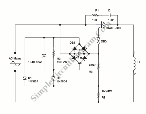
On the circuit diagram below show us a schematic of step-down circuit which is used to approximately divide by two the rms voltage between the line input and the inductive load (L1). C2 and R3 give a turn-on delay of approximately 7 ms. The diode bridge, with diodes D1 and D2 and R2 resistors have a function to discharge C2 […]
Read more